/ Resistance heating /
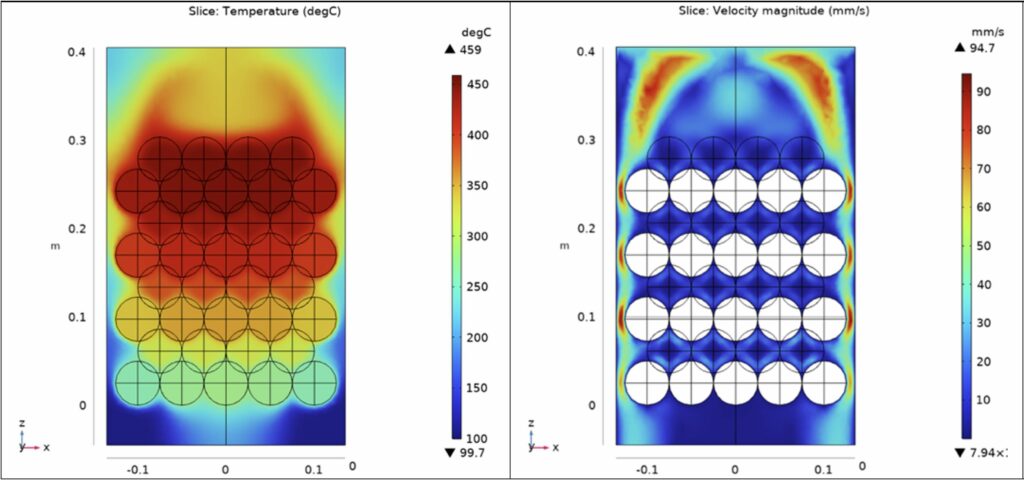
Electrical resistance heating, which is also known as Joule heating, resistive heating, or Ohmic heating, is the effect of producing heat by passing an electric current through a conductive material. Electric resistance heating is nearly 100% energy efficient in the sense that all the incoming electric energy is converted to heat. For electric heaters, there are various heating resistors available that can be used to convert electrical energy into thermal energy. A very simple form is a high-resistance wire, also called as heating conductor. Depending on the design of the resistor, the heating component will be a heating conductor, cartridge, coil, tape, register, sleeve or pad. For example, the heating cartridge is a cylindrical cartridge made of metal that contains a heating coil. The heating elements can be designed quite flexibly and can be used, among other things, for direct heating of industrial plants and machines. Heat for industrial processes can also be provided by heating process gases. Simple configurations are well-known in which, for example, a wire heated with electrical energy in a heating coil releases heat to a flow of air streaming past. Further implementation options for effective heating of gases in the high power range consist of applying an electric current to bulk materials (for instance pebble beds in Figure 1)) through which the gas to be heated flows. Owing to their robustness and flexibility such heating components are very well suited for a harsh industrial environment and will be considered within CITADEL. The advantages of resistance heating are the uniform and high temperature, the very short heating time, the high efficiency, the low maintenance and the reduced metal scale formation. Moreover, electric resistance heating systems are characterised by a high flexibility and a very fast and exact controllability by variations of current and electrical resistance.

Figure 1: Example for the design of an electrical resistance heater using a pebble bed: numerical simulations for the temperature field (left), and the velocity of the gas stream to be heated (right).
/ Microwave plasma heating /
In physics, a well-defined plasma is described as the fourth state of matter. It is made up of charge particles, ions, and electrons, as well as other excited gas species and highly reactive charge carriers. The microwave plasma discharge will occur over a wide range of gas pressures, beginning at mbar vacuum and ending at atmospheric pressure. Plasmas are classified as either equilibrium or non-equilibrium. In the equilibrium section, the temperatures of electrons and ions are roughly close to each other, whereas in non-equilibrium plasmas, the temperatures of electrons and ions differ greatly. Microwave plasmas are non-equilibrium plasmas because the electron temperature is around 11000K and the massive species temperature can range between 2000 and 6000K. Because of the high collision rate of charged particles in atmospheric pressure, particularly electrons, with background molecules, the atmospheric microwave plasma jet is a thermal plasma. The collision is the source of heat transfer from electron energy to the molecular energy.
The Figure 2 depicts the microwave plasma jet schematic. The microwaves that created with magnetron device, can interact with an insulation tube, such as a quartz tube. The igniter is a metal rod that is introduced into the microwave medium and creates an arc to create a gas discharge. Because plasma is a good absorber of microwaves, it continuously absorbs microwave energy. In microwave plasma jets, two types of gas flow are typically used. The swirl flow, also known as radial flow, and the axial flow. The main flow is radial, and it serves two functions: (i) Separate the plasma from the inner surface of the tube to prevent it from melting, (ii) Increase the residence time of the gas inside the tube to interact with microwaves more effectively.
The moving plunger is a metal plate in a specific position to apply the maximum electric field of microwave in the centre of the tube.
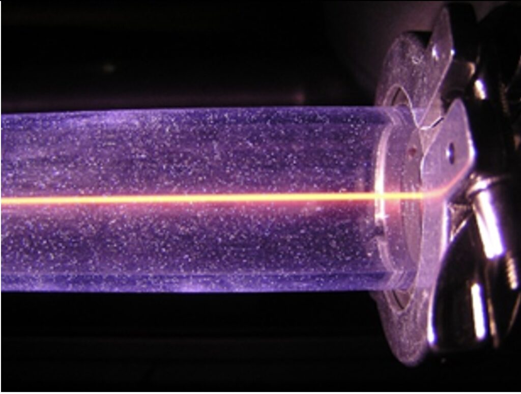
The 915MHz plasma jet is widely used in industrial heating with high power up to 100kW. A photograph of an operating unit generating such a 915MHz plasma jet is shown in Figure 2 (right). The power in microwave plasmas is reflected by plasma with electrons. The three stub Tuner is used to reduce reflection power and maximize plasma power absorption.

Figure 2: Schematic of the microwave plasma generation by Fricke & Mallah (left), 915MHz microwave plasma jet (right).
/ DC plasma heating /
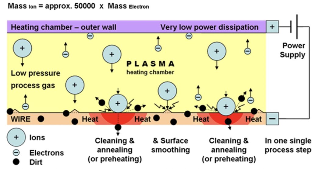
DC Plasma as glow discharge operate in rough vacuum, in the range between 0.01mbar and 100mbar. A schematic view of the basic process and the principle of DC Glow Discharge heating is presented in Figure 3. It allows for multi-stage processing of metals, especially as continuous process. The process is applied in Inert gas atmosphere, depending on the type of material to be processed. In case of copper it is Nitrogen, which doesn´t react with the surface and reduces the oxides from the material surface.
For this annealing technique, a conductive surface/material is required and the material is used as a grounded electrode surrounded by the annular electrode, which acts as the “hot” or driven electrode. Generally, Pulsed DC is applied for this process, combined with pulse inverting technique for better and more stable processing of the material. The energy provided from the power supply to the electrode is transferred nearly to 80% from the electrode to the material surface and is transformed there into heat energy. Figure 4 shows the effect of plasma annealing on the running material.


/ Oxy Fuel Burners /
Conventional gas burners, generally extended in the steel production, use air for the combustion of fuel which carries 79% ballast, almost all of which is nitrogen. The nitrogen is heated up in the combustion process and emitted in the flue gas, resulting in wasted energy, higher fuel consumption and CO2 emissions. As a consequence, for ladle preheating in steel making, the substitution of oxy-fuel burners increases fuel efficiency, allowing at the same time higher flame temperatures, which deliver much more of the heat from the burner into the process. Moreover, it hampers the radiative heat transfer from the products of combustion, which is the dominant mechanism at elevated temperatures. The use of oxy-fuel burners can reduce flue gas volumes 20-60%, with reduced baghouse loading and temperature; ultra-low NOx emissions can be achieved with a customized burner design and good operating practices.
